By definition, any type of drilled deep foundation is buried in the ground, hiding its constructed shape from visual inspection. This complicates the quality assurance process, leaving reasonable potential foundation performance questions. Fortunately, a very quick, reliable, and convenient means of indirect cast-in-situ pile visualization is available: The Thermal Integrity Profier or TIP.
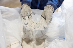
Thermal Integrity Profiing is a non-destructive integrity test method used for evaluating the post-construction quality of cast-in-place foundations. This method uses the temperature measurements, or hydration energy, from the curing cement to assess integrity. These measurements are obtained using embedded Thermal Wire® cables attached to the reinforcing cage for drilled shafts or to a center bar for smaller diameter auger castin-place (ACIP) piles. In general, reductions in temperature correlate to reductions in the effective radius or the presence of lower quality concrete/grout. Increases in temperature correlate to increases in cover or areas of increased cross-section. TAP boxes automatically record the temperature every 15 minutes at each thermal sensor location (one foot or 300 mm depth increments).
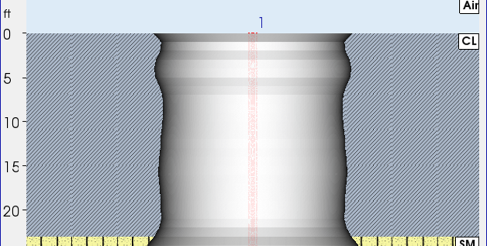
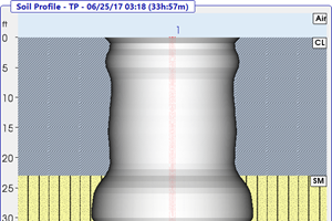
This process is typically complete within 10 to 48 hours after initial concrete/grout placement. On a project in Los Angeles, California, GRL Engineers, Inc., contracted by Shoring Engineers, was given a rare opportunity to observe the entire ACIP pile after construction. Project specifications required both a static load test to determine the bearing capacity and shaft resistance distribution (using embedded strain gages), and TIP for pile integrity evaluation. After completion of the tests, the contractor extracted the pile for inspection and comparison with the TIP predicted pile shape. The installed pile had a planned pile diameter of 18 inches (450 mm) and a length of 65 feet (19.8 m). The reported soil profile consisted of lean clay (CL) from 0 to 23 feet (7.0 m), underlain by silty sand (SM) from 23 to 40 feet (7.0 m to 12.2 m), and then again lean clay (CL) to the pile base.
The center bar was instrumented from 0 to 62 feet (18.9 m) with a single Thermal Wire® cable. The installed grout volume was reported to be 5.4 cubic yards (4.1 cubic meters) or approximately 127 percent of the theoretical volume. The as-constructed pile diameter was calculated using circumference measurements at one foot intervals from 5 to 62 feet (1.5 m to 18.9 m) below pile top. These visual inspections and field measurements indicated a relatively uniform pile from 5 to 21 feet (6.4 m) and from 40 feet (12.2 m) to the pile base. A sizable increase in the pile cross section was observed from 25 to 30 feet (7.6 m to 9.1 m). A second, smaller bulge in the pile was observed near 37 feet (11.3 m).
The “T-Soil” analysis method was utilized to calculate the effective pile diameter which is correlated from the measured temperature and total grout volume. This T-Soil method is recommended for single wire (i.e. center bar) applications on piles up to 24 inches (610 mm) in diameter. It differs from the analysis technique used for drilled shafts where temperatures are typically monitored on a reinforcing cage rather than a central location. A plot of the Effective Diameter vs. Depth based on both TIP and circumference measurements. Overall, the effective diameter based on the TIP results deviated by approximately 2 percent from the actual measurements over the instrumented length of the center bar.